Computational Fluid Dynamics in Heat Exchanger Design and Analysis
Recently we were approached by a customer that had several condensers installed which were giving performance problems. The condensers simply did not perform to their capacity. The customer was worried that the problem did not lie in the condenser design but in the product inlet header. The suspicion was that the product flow into the heat exchanger was not distributed evenly over all the tubes of the heat exchanger. It is well known that the wrong product distribution or flow over the inner tubes can lead to performance issues.
HRS offered to analyse the situation using a technique called Computational Fluid Dynamics (CFD). In CFD analysis numerical measurements and algorithms are used to study the flow of fluids through objects. The object and fluid are divided into finite elements or cells, each of which has finite dimensions. For each cell, the mass, momentum and energy are calculated and outcome of the calculation for one cell is the input for the calculation for the next cell. The smaller the dimensions of the cells, the more calculations are performed and the more accurate the result. In short, CFD allows us to perform numerical experiments in a virtual flow laboratory on a computer. More information on CFD can be found here.
Approaching the Problem
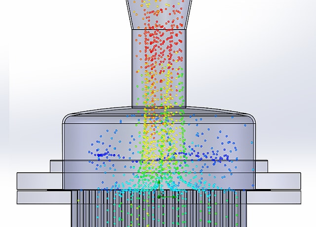
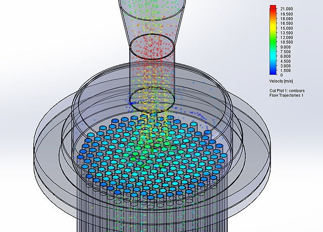
First, the heat exchanger with its inlet header was redesigned using 3D CAD software. The process fluid was analysed to obtain its physical properties, and, using a flow simulation software package with the CAD software, the behaviour of the fluid in the heat exchanger was calculated. The image above gives a representation of the fluid flow. Different colours indicate different velocities, clearly showing an array of fluid velocities in the flow path down the exchanger. By plotting the velocity at the inlet of each inner tube, the following picture emerges:
The colour scheme indicates velocities that vary from 12 m/s (in the centre e tubes) to 1.5 m/s (in the tubes on the outer ring). This showed that the customer’s suspicions about the inlet were correct and were responsible for the performance problems.
An Improved Solution to the Problem
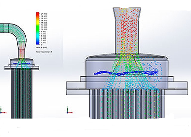
The question that comes next is: What can be done to improve the flow of the product through the heat exchanger? How can we create an even distribution of product across all the heat exchanger tubes? One option would be to extend the length of the inlet header so that the product has more time to distribute itself. The challenge, however was to come with a solution within the existing installation. So a further CFD analysis was performed on the same inlet header but this time with concentric reducers fitted in the flow path. The aim was to test if the reducer design would be able to divert fluid towards the outer ring of tubes and improve the flow distribution.
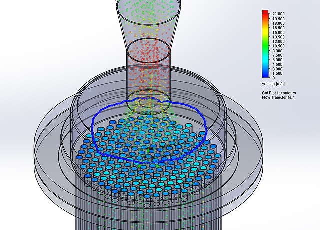
Again the velocities at the inlet of each inner tube were plotted. The colour scheme shows improvement, with velocities ranging from 1.5 to 6 m/s approximately. However, this was still not ideal as some tubes received insufficient flow.
Based on this first analysis and redesign, further design changes can be made until a final design is obtained. This case study shows how CFD is a very powerful tool for checking hypotheses about fluid behaviours. It also allows the design engineer to analyse prototypes inside a virtual laboratory before money is spent on prototypes and manufacturing. As you can see, using the latest Computational Fluid Dynamics (CFD) technologies provides savings in time and money which we are able to pass on to our customers.