How to Design a Tubular Heat Exchanger?
At HRS Heat Exchangers we design tubular heat exchangers every day. This section provides an overview of the process.
Step 1: Analysing the Application
When we first receive an enquiry for a heat exchanger, the first step is to analyse the application. Is it a food industry application? Is it an industrial one? The design engineer must correctly define the type of heat exchanger that is necessary and will meet the requirements of the application.
The design temperature, pressure and maximum allowable pressure drop must be defined for the product and service fluids.
Step 2: Identifying the Fluid Properties
The next step is to analyse the fluids or gases involved: the product side fluid and service side fluid. Four important physical properties of the fluids involved need to be known:
- Density
- Specific heat
- Thermal conductivity
- Viscosity
The correct way to proceed is to obtain values for these four parameters for various temperatures in the heating or cooling curve of the application. The better we understand the physical properties of the fluids involved, the more accurate will be the design of the heat exchanger.
Step 3: The Energy Balance
Once we have correctly defined the physical properties, it is time to check the energy balance. Normally the customer defines the product’s flow rate and the desired entry and exit temperature. They will indicate the type of serviced fluid to be used and define two of the following three parameters: service flow rate, service entry temperature or service exit temperature. With two of these known, the third parameter is calculated.
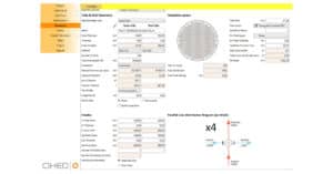
Step 4: Defining the Geometry of the Heat Exchangers
In this step, the design engineer defines the geometry of the heat exchanger. He will choose the shell diameter and will define the tube bundle that is placed inside the heat exchanger: nr of inner tubes, inner tube diameter and wall thickness and the length of the inner tubes. Secondly, the dimensions of the shell and tube side fluid connections are defined. At this stage also the choice of materials applied has to be made. By standard HRS Heat Exchanger applies stainless steels for shell and tubes side, but also other alloys can be applied.
Step 5: Thermal Calculation
At this stage, the design engineer performs a thermal calculation. The objective is to obtain the shell and tube side heat transfer coefficients. These coefficients depend on the four key fluid parameters and the velocity of the fluid. The relation between the parameters and the heat transfer coefficients is defined in a mathematical formula that is specific to the geometry (i.e. the type of heat exchanger used: tubular, plate, corrugated tube). HRS Heat Exchangers has its own specific formulas for use with corrugated tubes.
With the shell and tube side coefficients known, the overall heat transfer coefficient can be calculated. Knowing this value, it becomes possible to calculate the total heat transfer area needed for the application:
Area=Duty/[K×LMTD]
Where:
- Area: Total heat transfer area required, m².
- Duty: Total heat transferred, kcal/hr (derived from energy balance).
- K: Overall heat transfer coefficient, kcal/[hr.m².°C].
- LMTD: Log mean temperature difference, °C (the average logarithmic temperature difference between shell and tube side fluid over the heat exchanger length).
Another important parameter is the pressure drop, which is calculated for the shell and tube side fluids. The pressure drop is a function of the Reynolds number, the type of flow (turbulent or laminar flow) and the roughness value of the shell and inner tubes.
Step 6: Interpretation of the Thermal Calculation
The calculated area is compared with the area defined in step four and a check is made to see if the pressure drops are within the design limits. If the calculated area exceeds the predefined area, the geometry of the heat exchanger needs to be redesigned, possibly by increasing the length or adding inner tubes.
Likewise, if the calculated pressure drop exceeds the maximum defined, then a new geometry must be designed to ensure a pressure drop reduction. Steps four to six are then repeated until a satisfactory design with suitable geometry is obtained.
Step 7: Mechanical Design Calculations
With the heat exchanger geometry defined, the mechanical design calculations must be performed to ensure that the heat exchanger design is valid for the design pressure and conditions. The typical calculations are:
- Calculation of shell wall thickness.
- Calculation of nozzle wall thickness.
- Calculation of inner tube wall thickness.
- Calculation of expansion joint dimensions (to compensate for shell and tube side differential expansion due to temperatures differences.
- Calculation of tube sheet thickness.
The mechanical design calculations may result in wall thicknesses or other parameters that do not comply with the geometrical design defined in step 4. In this case, a new proposal for the geometry must be made and step 4 to 7 must be repeated.
Step 8: Preparation of the Manufacturing Drawings
With all dimensions of the heat exchanger defined, the manufacturing drawings can be prepared. The drawing package contains details of the various components of the heat exchanger, including shell; tubes, expansion joints, connections, etc.
Contact Us for more information