Wastewater Evaporation Plant
A chemical company in Spain that produces sulphuric acid, nitric acid and other chemicals approached us to resolve a serious environmental problem that they had involving the wash water used to clean the tanks where chemicals are stored.
Obviously no wash water could be drained to the river without being treated to eliminate all traces of hazardous chemicals.

Solution
We proposed a solution designed to utilize a unique effect of evaporation and a mechanical vapor recompression system to reduce energy consumption.
Evaporation is performed at 176℉, and the vapor obtained is compressed up to a pressure equivalent to 221℉ approximately. This vapor is then used to provide the evaporation energy by condensation in the evaporator. An additional electrical heating system was included for initially starting the process.
Based on our experience in similar applications, the plant is designed to work continuously with evaporation and recirculation through a buffer tank. The tank has a decanting bottom which accumulates crystals which are then extracted through the bottom of the tank.
In this case, the plant has a vapor capacity of 772lb/hr, but HRS Heat Exchangers can build similar systems between 440lb and 55,116 lb/hr.
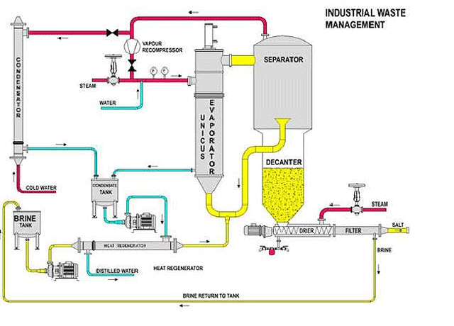
The evaporator is based on a Unicus Series dynamic heat exchanger to avoid fouling. The mixture of vapor and water containing salt crystals goes to a cyclonic separation chamber, where the vapor goes out through the top and the waste water goes down to the decanting hopper.
As explained above, there is a new liquid entry for recirculation in the evaporator, while the crystals go down to the bottom, where they are picked up by an extraction pump.
The vapor that comes out from the cyclonic separator is sent to a lobular vapor compressor that compress it to send it to the shell tube of the evaporator, where it condenses providing the necessary energy to continue the process.
Regulation and Control System
There is a PCL in the electro-pneumatic panel, with a LCD screen and an integrated keyboard for controlling the valves and plant engines. The regulation and working instructions are entered through the keyboard and the state of the plant and sensor readings are displayed on the screen. The control program allows for the continuous injection of the new product, along with evaporation and the unloading of concentrate. It also includes a cleaning cycle of the plant
Design Conditions
The system was designed within the following operating parameters and conditions:
- Product: wastewater
- Evaporation capacity: 772 lb/hr
- Evaporation temperature: 176℉
- Heating system: recompressed vapor
- Initial heating to get the regimen by electrical resistance
- Continuous working with recirculation
- Continuous unloading of crystal concentrate for crystal separation and liquid return
- Estimated energy consumption (for 772 lb/hr):
- Electricity : 119453.5 BTU (15°C)
- Compressed air: 1.09985 gal/min. at 72.52 psi