Advantages of Corrugated Tubes
A large number of industries use processes in which heat is transferred between different fluids (or gases). The basic principle of heat transfer is extremely simple: two fluids at different temperatures are placed in contact with a conductive barrier (the tube wall) and heat is transferred from the hotter fluid to the colder fluid until they reach the same temperature. In industrial processes this is carried out in heat exchangers of various types and styles usually purpose built for the process and site conditions of the application.
The driving force for heat transfer is the difference in temperature between the hot and cold fluids. The greater the difference, the higher the rate at which the heat will flow between them. With complex processing sequences, the designer must optimize the temperature levels at each stage to maximize the total rate of heat flow.
A second factor controlling the transfer of heat is the area of the conductive barrier provided for heat flow. The greater the area then the greater amount of heat which can flow in a given time for a given temperature difference within the heat exchanger. The designer has to minimize this area to provide cost effective solutions to his client. With skill the amount of area can be minimized and configured to reduce the containment volume and overall cost.
The third and perhaps the most important factor controlling the transfer of heat is the rate at which the heat flows into or out from each of the fluids. A high resistance to heat flow in either fluid will produce a slow overall rate of heat transfer. The level of resistance to heat flow results from many different factors including the inherent thermal characteristics of the fluids but can be influenced by the designer in a very positive way by the generation of turbulence within the fluids to prevent the creation of a thermally resistant static “boundary layer” of fluid in contact with the heat transfer surface.
The fourth factor, also under the control of the designer, is the flow of heat through the conductive barrier between the fluids. The material chosen has to be compatible with the fluids of the process, it must not corrode or contaminate a food product, it must have an appropriate level of mechanical strength to withstand working temperatures and pressures and it must have a low resistance to heat flow so that it does not become the overriding factor in the heat transfer process.
The mathematical equations which describe the process of heat transfer are fairly simple:
Where:
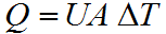
- Q is the amount of heat transferred, W
- A is the area for heat transfer, m²
- ∆T is an effective temperature difference, °K
- U is the overall heat transfer coefficient, W/m².°K
The value of U is slightly more complex to calculate:
Where:
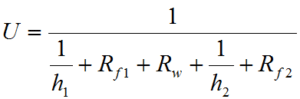
- h1 and h2 are the partial heat transfer coefficients, W/m².°K.
- Rw is the thermal resistance of the wall, m².°K/W.
- Rf1 and Rf2 are the fouling factors, m².°K/W.
While the values for Rf are usually specified by the client, the values of h and Rw can be influenced directly by the designer by the choice of tube size and thickness and the materials of construction. The values of the partial heat transfer coefficients h depend greatly on the nature of the fluids but also, crucially, on the geometry of the heat transfer surfaces they are in contact with. Importantly the final values are heavily influenced by what happens at the level of the boundary layers: the fluid actually in contact with the heat transfer surface.
Heat Transfer Processes
A lot of the academic research taking place into heat transfer processes concentrates on ways of predicting with accuracy the precise values of the boundary layer resistance and on ways of affecting the values without paying too high a penalty in terms of increased pressure losses.
Many techniques to reduce the tube side boundary layer resistance have been tried including various styles of tube “inserts” which take the form of complex wire shapes or flat twisted strips fitted inside the tubes and various styles of tube deformation. Most have the disadvantage of increasing the resistance to fluid flow, the pressure loss, at a rate which increases more rapidly than the decrease in boundary layer resistance.
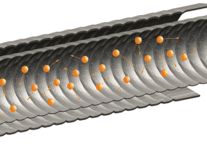
One technique which does not have this disadvantage, however, is that of deforming the tube with either a continuous spiral indentation or an intermittent spot indentation. Research has shown that by choosing the depth, angle and width of the indentation carefully, the rate of decrease in boundary layer resistance can exceed the rate of increase in pressure loss.
The continuous disturbance of the boundary layer of the tube side fluid increases the amount of turbulence within the fluid as described mathematically by the “Nusselt number” and, providing the tube side fluid has the higher resistance to heat flow, will increase the overall rate at which heat is transferred.
This turbulent behavior is illustrated in this video.