How To… Specify a Heat Exchanger
Heat exchangers are a well established tool for the thermal processing of materials. They are used for cooking, pasteurization and sterilization, as well as for heating or cooling a range of products.
When it comes to designing a heat exchanger, there are two main considerations. The first is to select the right type of heat exchanger: plate, tubular, corrugated tube, scraped surface, etc. Various factors will influence this choice, including the nature of the materials to be heated or cooled, the objective of the process (such as cooking or pasteurization) and any restrictions of the environment where the heat exchanger is to be used. The second consideration is size; it is imperative that the heat exchanger selected is correctly sized for the job.
TYPES OF HEAT EXCHANGERS
The three main types of heat exchanger are:
- Plate Heat Exchangers:
These consist of thin, corrugated plates packed inside a frame, with the product in alternate channels, and service fluid in between the product channels. They are ideal for applications where the fluids have relatively low viscosity with no particles. They are also an ideal choice where product outlet temperature is close to the service inlet temperature. Performance can be improved through clever design, such as using herringbone patterned heat transfer plates. These are assembled in an inverse formation to create two sets of parallel channels, one for each liquid. Since the herringbone patterns point in opposite directions, a high number of points of support are achieved, creating a lattice in each channel. This provides a high level of turbulence, which in turn leads to an elevated rate of heat transfer. - Tubular & Corrugated Tube Heat Exchangers:
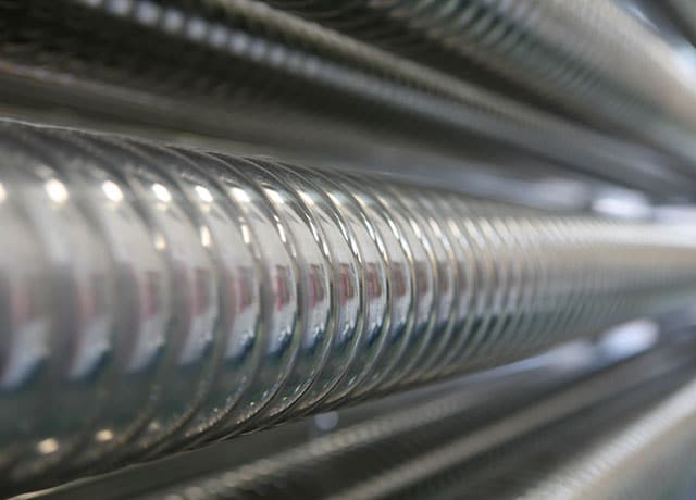
Tubular heat exchangers consist of one or more tubes within a shell, with the product flowing in the tubes and the service fluid flowing over the tubes (through the shell). By using corrugated tube technology, both heat transfer and efficiency are increased over standard smooth tube heat exchangers. In addition, potential fouling is minimized, making it possible to supply more compact and economical heat exchangers. Specific models have been developed for various types of industries, and are often manufactured from stainless steel for use in the food, pharmaceutical and chemical industries. - Scraped Surface Heat Exchangers:
These are used in applications where fouling causes heat transfer rates to drop, or when viscous fluids have very low heat transfer rates.Fouling occurs when fluids degrade near the tube wall and layers of solids are deposited the tube wall. These layers work as an insulator and prevent effective heat transfer. Another form of fouling is crystallization where, due to cooling or increasing concentration, components in the fluid are deposited on the heat exchanger surface. Scraping the heat transfer surface to remove these layers of fouling maintains high heat transfer rates in such situations.In general, the more viscous the fluid, the lower the heat transfer rate, so very viscous fluids require very large heat transfer areas. Scraped surface heat exchangers mix the fluid vigorously, which increases the amount of fluid coming into contact with the heat exchange surface. This increases the heat transfer rates and reduces the surface area required.
HEAT EXCHANGE CALCULATIONS
Once the correct type of exchanger has been chosen, the engineering staff of the supplier will need to make sure that the model supplied is correctly sized for the job. In other words, that it offers the right amount of heat transfer for the fluid/s being treated and at the throughput required.
It is possible to write an entire book on the science of heat transfer, and indeed many people have done so. However, the principle aim of the calculations used is to make sure that the heat exchanger has a large enough heat transfer area for the specified fluids, at the specified inlet and outlet temperatures. Most calculations will also be able to factor in variables such as whether the heat exchanger operates using counter-flow or co-current flow.
The basic heat design equation, which has been widely used for many years, is:
![]()
where:
Q is the rate of heat transfer between the two fluids in the heat exchanger
U is the overall heat transfer coefficient. This depends on the conductive properties of the fluids and the heat exchanger material
A is the heat transfer surface area
The value of U is harder to calculate:
![]()
where:
h1 and h2 are the partial heat transfer coefficients, W/m2.oK (tube and shell side)
Rw is the thermal resistance of the wall, m2.oK /W
Rf1 and Rf2 are the fouling factors, m2.oK /W (tube and shell side)
While the values for Rf are usually specified by the client, the values of h and Rw can be influenced directly by the designer depending on the choice of tube size and thickness, and the materials used for construction. The values of the partial heat transfer coefficients h depend greatly on the nature of the fluids but also, crucially, on the geometry of the heat transfer surfaces with which they are in contact. Importantly, the final values are heavily influenced by what happens at the level of the boundary layers: the fluid actually in contact with the heat transfer surface.
The driving force for heat transfer is the difference in temperature between the two elements. In the case of a tubular heat exchanger, the temperature of the two fluids changes as they pass through the heat exchanger.
LAMINAR AND TURBULENT FLOW
However, while this calculation is suitable for simple fluids passing through simple smooth tubular heat exchangers, it is of limited use in real life commercial situations. One of the reasons for making corrugated tube and scraped surface heat exchangers is that they are required for fluids and materials with complex properties, such as viscous and non-Newtonian fluids, or materials containing particles.
One of the important factors controlling heat transfer is the resistance to heat flow through the various ‘layers’ that form a barrier between the two fluids. There are effectively five of these layers which add resistance to the heat flow between the two fluids in the heat exchanger:
- The inside ‘boundary layer’ formed by the fluid flowing in close contact with the inside surface of the tube.
- The fouling layer formed by deposition of solids or semi-solids on the inside surface of the tube (which may or may not be present).
- The thickness of the tube wall and the material used, which will govern the resistance to heat flow though the tube itself.
- The fouling layer formed by deposition of solids or semi-solids on the outside surface of the tube (which may or may not be present).
- The outside ‘boundary layer’ formed by the fluid flowing in close contact with the outside surface of the tube.
The values used for items 2 and 4 can usually be supplied by the client based on experience, while the designer of the heat exchanger will select the tube size, thickness and materials to suit the application. The resistance to heat flow resulting from numbers 1 and 5, (known as the partial heat transfer coefficients) depends both on the nature of the fluids and the geometry of the heat transfer surfaces themselves.
One way to prevent the build-up of these layers in certain fluids is to increase the speed at which they pass through the heat exchanger so that turbulence is created and the boundary layer breaks away from the surface of the tube. This is the point at which so-called laminar flow (with the fluid passing through smooth layers, where the innermost layer flows at a higher rate than the outermost) becomes turbulent flow (where fluid does not flow in smooth layers but is mixed or agitated as it flows).
The velocity at which this occurs is influenced by many different factors, but in order to quantify it for the purposes of specifying heat exchanger properties, engineers use something called the Reynolds number.
REYNOLDS NUMBER
The Reynolds number is denoted by Re, and represents
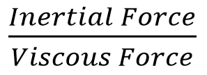
It is calculated as follows:
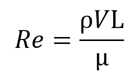
where:
is the density of the fluid
V is the velocity of the fluid
L is the length or diameter of the fluid
µ is the viscosity of the fluid
Reynolds numbers of less than 2,000 describe laminar flow, while numbers above 10,000 describe turbulent flows. Between the two values is an area of uncertainty called the transitional zone where there may or may not be turbulence generated depending on a number of unpredictable factors. In practice, engineers try to provide solutions outside of this zone. Another option is to deform the tube, which introduces higher levels of turbulence in the transition and turbulent flow area. This is the main reason for using corrugated tube heat exchangers.
Laminar Flow
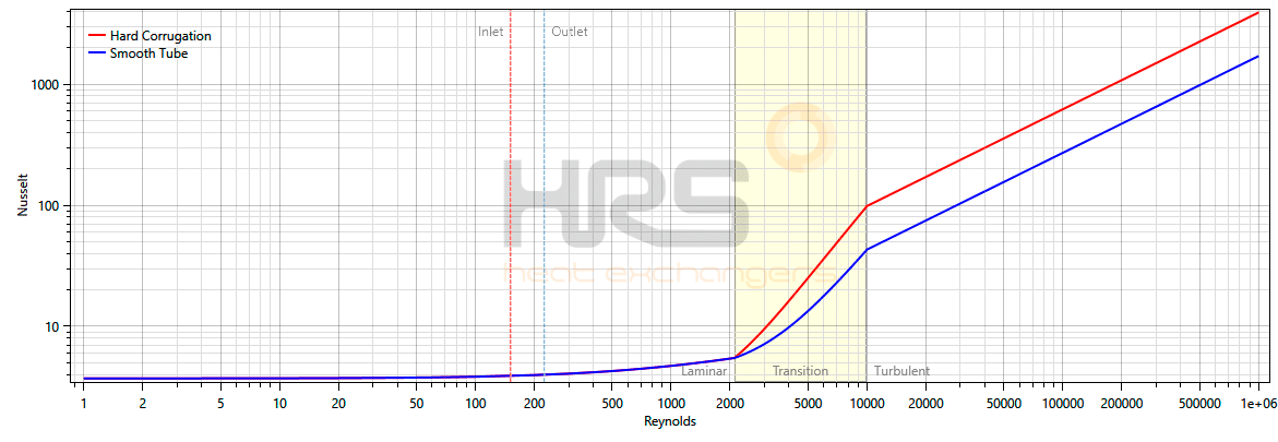
The blue line in the graph is for a smooth tube while the red one is for a corrugated tube. As can be seen, whether or not the tubes are corrugated, when operating in a laminar flow regime corrugated tubes have no positive effect until the Reynolds number is above 2,000.
Transitional Zone
At values of Reynolds numbers between 2,000 and 10,000, there is a zone of uncertainty called the transitional zone where there may or may not be turbulence generated depending on other unpredictable factors. As it is an area of uncertainty heat transfer, engineers try to avoid fluids flowing in this area.
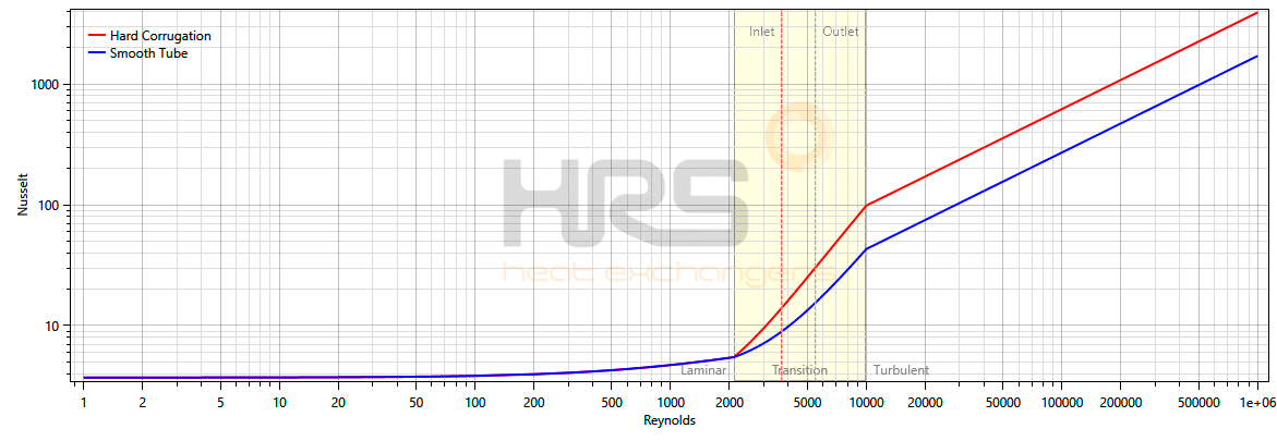
As can be seen in this case, when the tubes are corrugated, they provide a significant enhancement when the Reynolds number is above 2,000 but still below the 10,000 level required for turbulent flow with a smooth tube.
Turbulent Flow
At Reynolds numbers above 10,000 there is substantial breaking away from the tube wall. This condition is described as turbulent flow, with significant mixing of the boundary layer and the bulk fluid. This is the most efficient area for heat exchangers to work in.
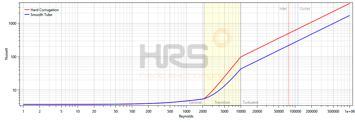
This graph shows that corrugation in turbulent flow regimes has a significant enhancing effect for Reynolds numbers above 10,000 when compared to the equivalent smooth tubes.
In summary, the corrugation of the inner tubes significantly increases the rates of heat transfer in the transition and turbulent flow area. Under the right circumstances, the amount of heat transfer can be doubled (note that the Y-axis in the graph is exponential), which means a 50% reduction of required surface area therefore a significant cost saving.
FOULING FACTORS
The fouling factors to be used in the design of heat exchangers are normally specified by the client based on their experience of running the plant or process. If uncontrolled, levels of fouling can negate any benefits produced by careful heat exchanger design. The fouling factor represents the theoretical resistance to heat flow due to a build-up of a layer of dirt or other fouling substance on the tube surfaces of the heat exchanger, but they are often overstated by the end user in an attempt to minimize the frequency of cleaning. In reality, if the wrong fouling factor is used, cleaning may actually be required more frequently.
Fouling mechanisms vary with the application but can be broadly classified into four common and readily identifiable types:
Chemical fouling:
This occurs when chemical changes within the fluid cause a fouling layer to be deposited onto the tube surface. A common example is scaling in a kettle or boiler caused by ‘hardness’ salts depositing onto the heating elements as the solubility of the salts reduce with increasing temperature. This is outside the control of the heat exchanger designer but can be minimized by careful control of the tube wall temperature in contact with the fluid. When this type of fouling occurs it must be removed by either chemical treatment or mechanical de-scaling processes (wire brushes or even drills to remove the scale, or sometimes high-pressure water jets).
Biological fouling:
This is caused by the growth of organisms within the fluid which deposit onto the surfaces of the heat exchanger. Again, this is outside the direct control of the heat exchanger designer, but can be influenced by the choice of materials as some, notably the non-ferrous brasses, are poisonous to some organisms. When this type of fouling occurs it is normally removed by either chemical treatment or mechanical brushing processes.
Deposition fouling:
This is when particles contained within the fluid settle out onto the surface when the fluid velocity falls below a critical level. To a large extent this is within the control of the heat exchanger designer, as the critical velocity for any fluid/particle combination can be calculated to allow a design to be developed with minimum velocity levels higher than the critical level. Mounting the heat exchanger vertically can also minimize the effect as gravity would tend to pull the particles out of the heat exchanger away from the heat transfer surface, even at low velocity levels. When this type of fouling occurs it is normally removed by mechanical brushing processes.
Corrosion fouling:
This is when a layer of corrosion products build up on the surfaces of the tube forming an extra layer of usually high thermal resistance material. By careful choice of construction materials the effects can be minimized, as a wide range of corrosion resistant materials based on stainless steel and other nickel-based alloys are now available to the heat exchanger manufacturer.
THE DESIGN PROCESS
Once all of the necessary data has been collected, the actual process of designing a heat exchanger can begin. Firstly, the application is assessed in order that the design engineer must correctly define the type of heat exchanger that is necessary and that it will meet the requirements of the application.
Energy Balance:
Then, using the known data for the fluids or gases to be heated or cooled, the energy balance of the process can be checked. Normally the customer defines the product’s flow rate and the desired entry and exit temperature. They will indicate the type of serviced fluid to be used and define two of the following three parameters: service flow rate, service entry temperature or service exit temperature. With two of these known, the third parameter can be calculated.
Defining the Heat Exchanger Geometry:
In this step, the design engineer defines the geometry of the heat exchanger. He or she will choose the shell diameter and define the tube bundle that is placed inside the heat exchanger: the number of inner tubes, inner tube diameter and wall thickness, and the length of the inner tubes. Secondly, the dimensions of the shell and tube side fluid connections are defined. At this stage the choice of materials applied also has to be made. HRS Heat Exchangers use stainless steels as standard for shell and tube sides, but other alloys can be applied and different materials will affect the energy calculations.
Thermal Calculation:
The objective of this stage is to obtain the shell and tube side heat transfer coefficients. These coefficients depend on the four key fluid parameters and the velocity of the fluid. The relation between the parameters and the heat transfer coefficients is defined in a mathematical formula that is specific to the geometry (i.e. the type of heat exchanger used: tubular, plate, corrugated tube). For example, HRS Heat Exchangers has its own specific formula for use with corrugated tubes.
With the shell and tube side coefficients known, the overall heat transfer coefficient can be calculated. Knowing this value, it becomes possible to calculate the total heat transfer area needed for the application, as shown earlier:
![]()
Another important parameter is the pressure drop, which is calculated for the shell and tube side fluids. The pressure drop is a function of the Reynolds number, the type of flow (turbulent or laminar flow) and the roughness value of the shell and inner tubes. Likewise, if the calculated pressure drop exceeds the maximum defined, then a new geometry must be selected to ensure a pressure drop reduction.
Mechanical Design Calculation:
With the heat exchanger geometry defined, the mechanical design calculations must be performed to ensure that the heat exchanger design is valid for the design pressure and conditions. The typical calculations are:
- Calculation of shell wall thickness.
- Calculation of nozzle wall thickness.
- Calculation of inner tube wall thickness.
- Calculation of expansion joint dimensions (to compensate for shell and tube side differential expansion due to temperatures differences).
- Calculation of tube sheet thickness.
The mechanical design calculations may result in wall thicknesses or other parameters that do not comply with the geometrical design defined above. In this case, a new proposal for the geometry must be made and the appropriate steps repeated.
With all dimensions of the heat exchanger defined, the manufacturing drawings can be prepared. The drawing package contains details of the various components of the heat exchanger, including shell, tubes, expansion joints, connections, etc.
Much of the commonly used literature use to build calculations and model heat exchanger performance can be up to 80 years old, and does not always reflect the most recent science. Also, while there is scientific literature for the behaviour of fluids in smooth and corrugated tubes, there is little published data on scraped surface heat exchangers. For this reason, HRS continues to use the very latest data in order to continually review and improve the calculations used for heat exchanger specification and design.