Correct Design for Batch Heat Exchanger Systems
In this case study, we take a detailed look at heat exchanger system for batch operations. In these systems, the material contained in a vessel is pumped through an external heat exchanger for cooling or heating. For a correct batch system design, many variables come into place and mistakes can easily be made. In this article, we review the parameters needed for the correct design and layout for optimal operation.
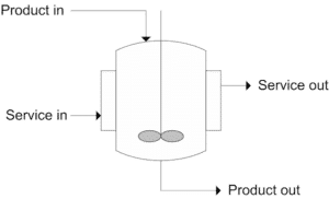
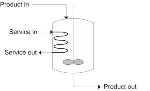
Batch heating or cooling systems are found in many places in modern industry (process, food, pharmaceutical etc). In these systems, a vessel is filled with content and needs to be heated or cooled in a predefined time period. It is important to make a distinction between directly heating the vessel (using a jacket or internal coil) or indirect heating using an external heat exchanger and product recirculation pump.
Introduction
Batch heating or cooling systems are found in many places in modern industry (process, food, pharmaceutical etc). In these systems a vessel is filled with content and needs to be heated or cooled in a predefined time period. We can make a distinction between direct heating of the vessel (jacket or internal coil) or indirect heating using an external heat exchanger and a product recirculation pump. See the figure below.
The advantages of using an external heat exchanger include:
- By choosing the correct product recirculation flow it is possible to design a heat exchanger with sufficient high velocity on the product side. This helps to keep the heat transfer rates high and helps to reduce the negative effects of heat transfer fouling.
- It is easier to design a setup with large heat transfer.
- Existing tanks without a jacket or coil, can be retrofitted to batch heating or cooling systems by adding a pump, heat exchanger and pipe work.
System Definition
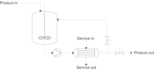
The next figure shows a detailed setup of a batch system with external heat exchanger.
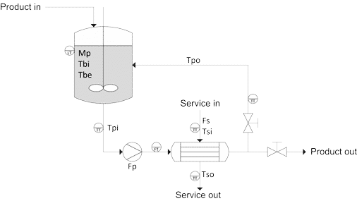
- In the figure the vessel is filled with product to the desired level. Mb is the total batch mass (kg). Tbi is the initial batch temperature (°C). Tbe is the desired batch end temperature (°C).
- The pump is started and product is re-circulated. Fp is the product’s flow rate (kg/hr).
- Service fluid is fed to the heat exchanger. Fs is the service fluid flow rate (kg/hr). Tsi is the service inlet temperature (°C). Tso is the service outlet temperature (°C).
- Slowly the batch is heated or cooled (depending on application.) Tpi is the inlet temperature to the heat exchanger (°C). Tpi is equal to the batch temperature. It is assumed that the agitator assures a good mixing and homogeneous temperature of the complete batch.
- When the Tbe is reached, recirculation of product is stopped and the vessel content is emptied.
- Instrumentation placed at key points (flow, temperature and level transmitters, FT, TT, LT) make it possible to monitor the process parameters and control the process.
- It is possible to work with different types of service fluid: Isothermal service fluid means working with a fluid that undergoes a phase change. For example, steam used for heating. A non isothermal service fluid means working with a fluid that is not changing its phase; for example water for heating or cooling that is not brought to boiling or freezing temperatures.
Design Guidelines
When designing a batch heating or cooling system, the problem is usually presented as:
Heating of 1 m³ of water from 20 to 90°C using superheated water as service fluid. Batch heating time required: 30 minutes maximum.
For the design of such a batch system there are many variables to play with. Below we have highlighted the most important design parameters involved and provided some basic rules that will help the design engineer to come to the best system solution.
Total System Mass
In a batch heating or cooling system, the material involved in the vessel, piping, pump and heat exchanger will be a part of the heat transfer process. In the example given above, these materials will heat up from 20 to 90°C as well. So part of the heat released by the superheated water is absorbed by the surrounding materials. Normally, this percentage of heat absorbed, is much less then the heat absorbed by the batch mass.
The heat input to the system mass is a small fraction of the total heat input, but it must still be evaluated as source of potential heat input loss to elements other than the vessel’s content. The correct way is to calculate/estimate the system mass and specific heat and use this input in the batch heating calculation.
Product Recirculation Flow, Fp
Fp is an important parameter. A change in Fp has a direct influence on the batch time needed. It is recommended that batch time is sufficient for the complete batch mass to be pumped through the heat exchanger several times. For example, with a 1,000 litre batch with a 1 hr treatment time and an Fp value of 1,000 litre/hr, each litre of product only passes through the heat exchanger once on average. Changing to a 3,000 l/hr flow rate, means that each litre of material passes through the heat exchanger three times. A reduction in product flow rate means a greater heat transfer area is needed to meet the required batch time.
We have seen cases where a 50% reduction of Fp required the installation of 30% more heat transfer area. In general, the extra investment for heat transfer area is more than the cost saved for a pump with less capacity.
Care should also be taken not to select Fp values that are too high as this could lead to increased pumping costs. The capital investment is reduced but operational costs can be much higher.
As a general rule, we recommend to start designing with a flow rate that will pump the batch mass approximately three times round during the batch time needed.
Service Fluid Flow, Fs
To analyse the service fluid flow we have to make a distinction between isothermal and non-isothermal service fluids.
For isothermal service fluids the batch time does not depend on Fs. When steam heating is used, the amount of steam condensed depends on the heat transfer capacity of the heat exchanger: U x A and the temperature difference between the service and the product flow.
- U = heat transfer coefficient (kcal/hr.m².°C)
- A = heat exchanger area (m²)
As the system is isothermal on service side, the temperature difference between service and product does not change due to a change in service flow rate.
For non-isothermal service fluids the situation is different. A reduction in Fs can cause a bigger temperature difference between service inlet and outlet temperature and the average temperature difference between service and product will decrease. Heat transfer capacity is affected and the batch time will increase. The fluid velocity in the heat exchanger will also decrease, leading to a reduction of the heat transfer coefficient. To compensate, more heat transfer area must be installed.
We recommend starting the design process with values for Fs between two to three times the value of Fp.
Service Fluid Temperature, Ts
Normally the service fluid temperature cannot be changed. Cooling or heating water can be made available from a central system that provides services for various installations in the plant and the temperatures cannot be changed for individual batch system. This is not the case when working with boiler steam for example. Boilers provide steam at pressure of 6 to 8 bar and at the point of steam consumption; the steam temperature can be regulated by installing pressure reduction and or control valves. In general, the higher the steam temperature, the higher the temperature difference between service and product and the shorter the batch times.
However, it is important that the service temperature is not so high that overheating of the batch product occurs. Similar situations can occur in cooling applications with the risk that products can be brought to temperatures below their freezing point. For example:
1000 kg of product of water solution (boiling point 100°C) with a specific heat of 1 kcal/kg.°C, to be heated from 20 to 80°C with boiler steam in 30 minutes. The system mass equals 200 kg of stainless steel with a specific heat of 0.12 kcal/kg.°C. The recirculation pump has maximum flow rate of 3000 kg/hr.
The design engineer provides a solution that involves a steam temperature of 120 °C and a heat exchanger of 1.5 m² and a heat transfer coefficient of 2000 kcal/hr.m².°C. He calculates a batch heating time of 29 minutes and 41 seconds. He forgets to calculate the product outlet temperatures at the heat exchanger exit. Would he have done that, then this is the table of temperatures that he would have obtained:
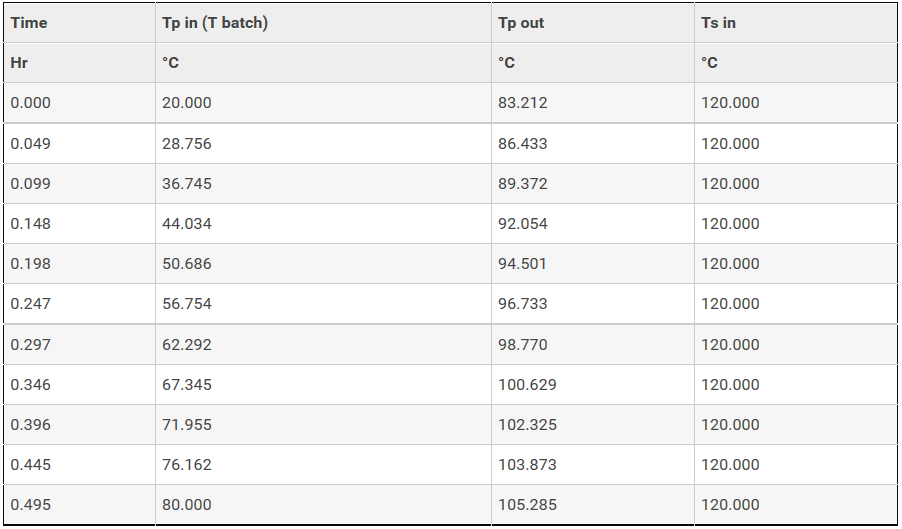
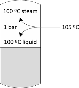
After roughly 18 minutes the product outlet temperatures reach values >100°C and water will evaporate (a flash occurs) if the tank is operated under atmospheric conditions.
In case the product is injected in the bottom of the vessel in the batch fluid, then gas bubbles can form as part of the product evaporates. This could lead to problems such as unwanted foaming.
By installing a steam control valve it is possible to lower the steam temperature, but a better solution to the problem would be to change the pump and work with a higher product recirculation flow rate. By doubling the flow rate to 6000 kg/hr we can lower the heat transfer area to 1.1 m² and still avoid overheating of the product. At 6000 kg/hr the total batch mass is pumped three times around in the batch period of 30 minutes. This coincides with the recommendation given in the previous analysis of the product recirculation flow.
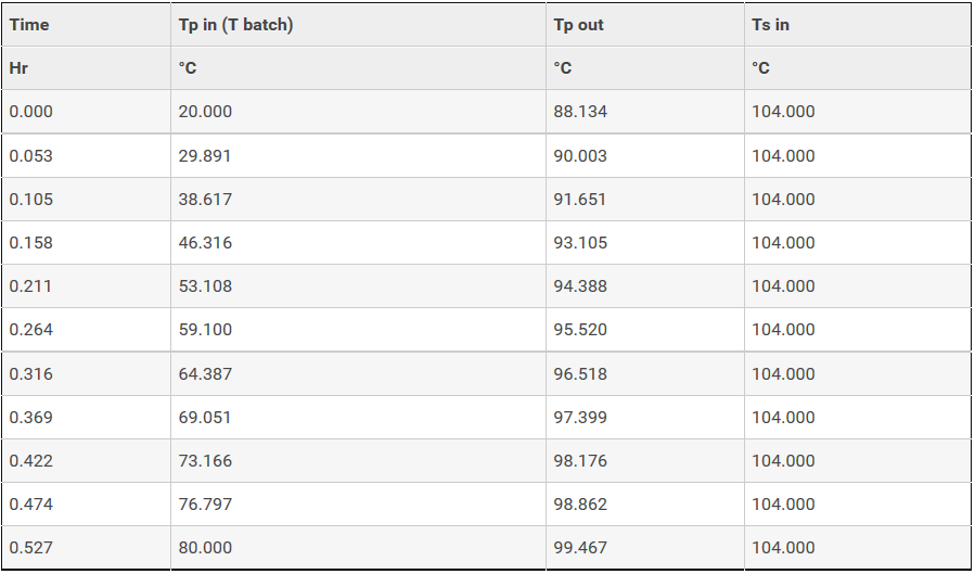
The total batch heating time is just a little over 30 minutes but the exit temperature of the product has not exceeded the boiling point.
A better solution to the problem would be to change the pump and work with a higher product recirculation flow rate. By doubling the flow rate to 6000 kg/hr we can lower the heat transfer area to 1.1 m² and still avoid overheating of the product:
At 6000 kg/hr the total batch mass is pumped three times around in the batch period of 30 minutes. This coincides with the recommendation given in the previous analysis of the product recirculation flow.
We strongly recommend always checking the product’s outlet temperature at the heat exchanger and making sure that it stays below maximum acceptable values.
Heat Transfer Coefficient and Heat Transfer Area, U and A
These two parameters are closely related in the design process. Normally product and service flow rates are defined first and then the heat transfer calculation is performed. With U known, a value of A is chosen which corresponds to the desired batch treatment time. Values of A that are too high will lead to expensive heat exchangers. The choice can then be made to change the process conditions so that U increases and A can be reduced.
Another way of reducing the heat transfer area needed is to change the service temperature in order to get a bigger difference between service and product, however, as we have already seen this can lead to unwanted effects, so caution is needed.
For fluids with stable physical properties over the temperature range, a good approximation is to calculate U at the middle temperature of the batch process.
For liquids with varying values the recommendation is to calculate U for the start and end conditions of the batch process and then calculate the average U value of the two, to be used in the batch time calculation.
Examples of systems with changing U values include:
- Batch heaters using steam which will show higher heat transfer coefficients at the end of the batch than at the beginning.
- Batch cooling application can show big changes in the viscosity of the product. This is often seen in food industry application with products where the increased viscosity at the end of the batch cooling process reduces the heat transfer coefficients.
Space Limitations
From an economic point of view, tubular heat exchangers for batch processes are best designed to be longer with a smaller shell diameter, rather than being shorter with bigger shell diameter.
If there are no space limitations then aim for tubular heat exchangers with longer lengths.
For plate heat exchangers the situation is different as these are very compact by nature and can be designed in much smaller spaces. However, certain applications require tubular heat exchangers. If space is limited then there are alternative solutions:
Multi-pass heat exchanger:
Multi-pass heat exchangers are a good solution for batch applications with isothermal service fluids.
For batch systems with non-isothermal service fluid, avoid temperature crosses as much as possible.
If multi-pass units are not an option, then a design can be laid out with various single pass heat exchanger modules in series, joined together with interconnecting bends. This way, the combined setup can provide the total thermal length needed in pure counter current flow in a smaller space. The maximum module length is defined by the space limitations.
Single pass modules with reduced lengths, connected in series, are a good solution for batch applications with temperature crosses and space limitations.