Comparison of Laminar and Turbulent Flow
Heat Transfer Flow Regimes
One of the important factors controlling heat transfer is the resistance to heat flow through the various “layers” that form the barrier between the two fluids.
The driving force for heat transfer is the difference in temperature levels between the hot and cold fluids, the greater the difference the higher the rate at which the heat will flow between them and the designer must optimise the temperature levels at each stage to maximise the total rate of heat flow.
The resistance to the heat flow is formed by 5 layers as follows:
- The inside “boundary layer” formed by the fluid flowing in close contact with the inside surface of the tube.
- The fouling layer formed by deposition of solids or semi-solids on the inside surface of the tube (which may or may not be present).
- The thickness of the tube wall and the material used will govern the resistance to heat flow though the tube itself.
- The fouling layer formed by deposition of solids or semi-solids on the outside surface of the tube (which may or may not be present).
- The outside “boundary layer” formed by the fluid flowing in close contact with the outside surface of the tube.
The values to be used for [2] and [4] are usually specified by the client as the result of experience while the designer will select the tube size, thickness and materials to suit the application.
The resistance to heat flow resulting from [1] and [5], (designated the partial heat transfer coefficients) depend greatly on the nature of the fluids but also, crucially, on the geometry of the heat transfer surfaces they are in contact with. Importantly the final values are heavily influenced by what happens at the level of the boundary layers, the fluid actually in contact with the heat transfer surface.
The Boundary Layers
When a viscous fluid flows in contact with a tube at low velocity it will do so in a way which does not produce any intermixing of the fluid: the boundary layer, the fluid in contact with the tube, will have its velocity reduced slightly by viscous drag and heat will flow through the fluid out of (or into) the tube wall by conduction and/or convection.
As the velocity of the fluid is increased it will eventually reach a level which will cause the fluid to form turbulence eddies where the boundary layer breaks away from the wall and mixes with the bulk of the fluid further from the tube wall.
The velocity at which this occurs is influenced by many factors, the viscosity of the fluid, the roughness of the tube wall, the shape of the tube, size of the tube etc. In order to quantify the turbulence (or lack of it) in practical terms heat transfer Engineers use a dimensionless number called the Reynolds number which is calculated as follows:
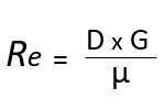
Where:
- D = the hydraulic diameter of the tube (m)
- G = the Mass velocity (kg/m².s)
- µ = the viscosity of the fluid (kg/m.s)
Laminar Flow
By experimentation, it has been found that Reynolds numbers of less than 2000 describe the condition at which there is no breaking away from the tube wall which is termed laminar flow. The physical properties of the fluid are the determining factors for the heat transfer in this area which is inefficient in heat transfer terms.
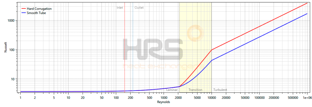
The blue line in the graph is for a smooth tube while the red one is for a corrugated tube. As can be seen, whether or not the tubes are corrugated, when operating in a laminar flow regime corrugated tubes have no positive effect until the Reynolds number is above 2,000.
Transitional Zone
At values of Reynolds number between 2,000 and 10,000 is a zone of uncertainty called the transitional zone where there may or may not be turbulence generated depending on other unpredictable factors. As it is an area of uncertainty heat transfer Engineers try to avoid fluids flowing in this area.
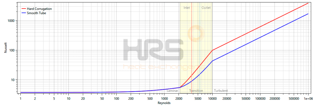
As can be seen in this case, when the tubes are corrugated, they provide a significant enhancement when the Reynolds number is above 2,000 but still below the 10,000 level required for turbulent flow with a smooth tube.
Turbulent Flow
At Reynolds numbers above 10,000 there is substantial breaking away from the tube wall and the condition is described as turbulent flow with significant mixing of the boundary layer and the bulk fluid. This is the most efficient area for heat exchangers to work in.
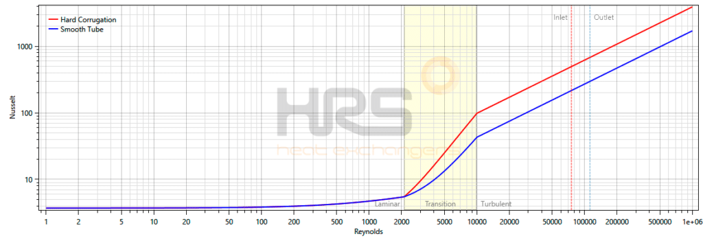
This graph shows that corrugation in turbulent flow regimes has a significant enhancing effect for Reynolds numbers above 10,000 when compared to the equivalent smooth tubes.
Many techniques have been tried in order to reduce the Reynolds number at which turbulent flow is produced but most have the disadvantage of increasing the resistance to fluid flow: the pressure loss, at a rate which increases more rapidly than the decrease in boundary layer resistance. Some cannot be used if there are solids present, others if the fluid is very viscous.
One useful technique which does not have the disadvantages of others is deforming the tube with a continuous shallow spiral indentation or an intermittent spot indentation. Research has shown that by choosing the depth, angle and width of the indentation carefully, the Reynolds number at which turbulent flow is produced can be reduced significantly below 10,000.
At values of Reynolds number above 10,000 this form of deformation also significantly increases the amount of turbulence and therefore the rate of heat transfer which can, when balanced correctly with the other factors reduce the surface area requirement and therefore the cost of the heat exchanger.
This is why we make corrugated tube heat exchangers.
Contact Us for more information